Recording
This chapter covers everything you need to know about capturing audio in Coherence Audio: selecting and configuring devices, understanding the recording controls, monitoring levels in real time, and what happens when hardware problems occur mid-session.
Overview
Coherence Audio records every device as a completely independent audio stream. There is no shared buffer, no mixing engine, and no master clock that all devices must lock to (unless you enable drift correction — see Clock Sync & Drift Correction). Each device writes its audio to its own raw data file, at its own native sample rate and bit depth, continuously from the moment you click Record until you click Stop.
This architecture has a practical consequence: if one device has a problem — a cable disconnect, a buffer overrun, a driver hiccup — it does not affect any other track. The other devices keep recording uninterrupted.
Note on WASAPI shared mode: Coherence Audio uses Windows WASAPI in shared mode rather than exclusive mode. Shared mode allows Windows and other applications to share the audio device simultaneously, which is important for not blocking system audio. Exclusive mode was evaluated but found to introduce more instability and data discontinuities in practice, so shared mode is used.
Selecting and Adding Devices
Auto-Population on New Project
When you create a new project, Coherence Audio automatically creates a track for every detected audio input device and arms each track. You are ready to record immediately.
Adding Additional Devices
Click Add Track (the + button in the toolbar or track panel). A device picker lists all currently available WASAPI audio input endpoints. Select a device and confirm.
There is no hard limit on the number of tracks — the practical ceiling is determined by your PC’s USB bandwidth, the number of available USB host controllers, and storage write throughput.
Multiple identical microphone models: Windows assigns every physical USB audio device a unique endpoint ID, so Coherence Audio will list them separately even if they are the same make and model. Label tracks with meaningful names (person’s name, instrument, position) early to avoid confusion.
Removing a Track
Right-click the track row header and choose Remove Track (or use the toolbar button). This removes the track from the session.
Rescanning for New Devices
If you plug in a microphone after the application is already open, or after a USB device was disconnected and reconnected, use Device → Rescan Input Devices. Coherence Audio will re-enumerate all WASAPI endpoints, refresh the device list, and attempt to re-link any tracks whose device was missing.
Per-Device Settings
Each track has its own independent set of audio capture parameters. Access them via the Settings icon on the track row, or through Settings → Known Devices.
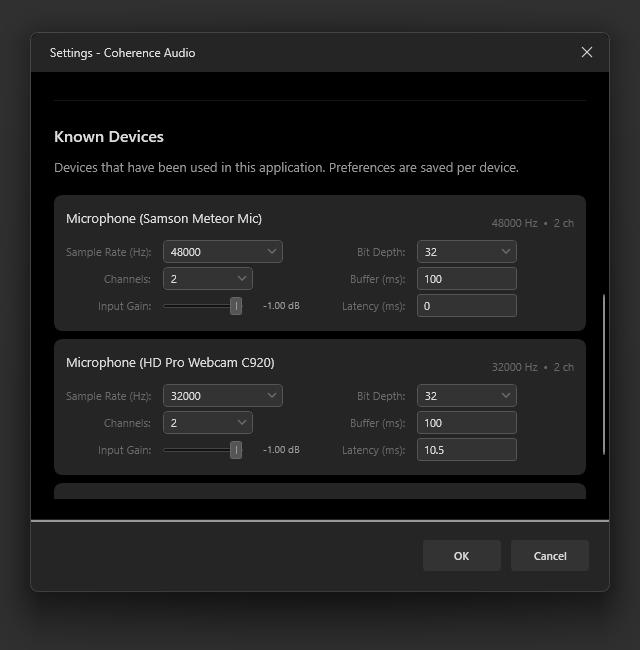
Sample Rate
The sample rate determines how many audio samples are captured per second. Common options:
| Sample Rate | Typical Use Case |
|---|---|
| 44,100 Hz | CD-quality; many consumer USB microphones default here |
| 48,000 Hz | Broadcast/video standard; most prosumer mics and interfaces |
| 96,000 Hz | High-resolution audio; some professional interfaces |
Important: Always set the sample rate to the device’s native rate. Asking a device to record at a rate it does not natively support causes the driver to resample internally, which can degrade audio quality.
Bit Depth
| Bit Depth | Dynamic Range | Notes |
|---|---|---|
| 16-bit PCM | ~96 dB | Sufficient for voice; smallest file size |
| 24-bit PCM | ~144 dB | General-purpose studio recording |
| 32-bit PCM | ~192 dB | Maximum integer headroom |
| 32-bit Float | Very wide | Default; handles unexpected level spikes gracefully |
Channels
Set to Mono for a single-capsule microphone (most USB microphones). Set to Stereo only if the device provides two channels (e.g., a stereo interface, a stereo USB mic with separate left/right capsules).
Buffer Size (ms)
The buffer size is a hint Coherence Audio passes to the Windows WASAPI driver, telling it the preferred capture interval — how frequently Windows should deliver audio packets from the device. A smaller value means the driver delivers audio more often (lower latency); a larger value means less frequent deliveries. The actual interval Windows uses may differ from the hint.
The default of 100 ms works well for most setups. You can change this per device in Settings → Known Devices.
Note: The internal memory ring buffer used to absorb transient disk slowdowns is fixed at 3 seconds of audio and is not user-configurable.
Latency Compensation (ms)
If one of your devices has a measurable fixed delay relative to others — for example, because its driver adds extra buffering — you can enter a value here to shift that track’s clips earlier on the timeline after recording.
How to measure latency offset: The most reliable method is to make a sharp transient sound (a hand clap, a pencil tap on the desk) in front of all microphones simultaneously before the actual recording starts. After recording, zoom into the clap on each track in the timeline and measure the time offset between the waveform peaks. Enter the measured offset for each non-reference track.
Latency compensation is applied automatically after recording stops and can be undone with Ctrl+Z.
Input Gain
This adjusts the Windows audio endpoint input volume for the device — the same control you would find in Windows Sound settings. The exact effect depends on what the driver does with the volume: some devices apply it in hardware (analog gain), others in firmware or software. For consistent behavior, set gain using the microphone’s own physical control where possible, and use this slider only for fine adjustment.
Arming and Disarming Tracks
Only armed tracks are captured when you click Record. An unarmed track is present in the session but will not record new audio.
Click the arm checkbox on the track row to toggle arm state. Armed tracks are highlighted; disarmed tracks are dimmed.
Note: Tracks cannot be armed or disarmed while recording is in progress.
VU Meters
Every armed track displays a VU meter while recording, showing peak levels in real time.
- The clip indicator (a red segment at the very top of the meter) lights when the input signal has clipped the ADC. If you see the clip indicator, reduce the input gain for that device.
- Monitor the levels before recording. Aim for peaks that sit clearly below the clip point during normal loudness.
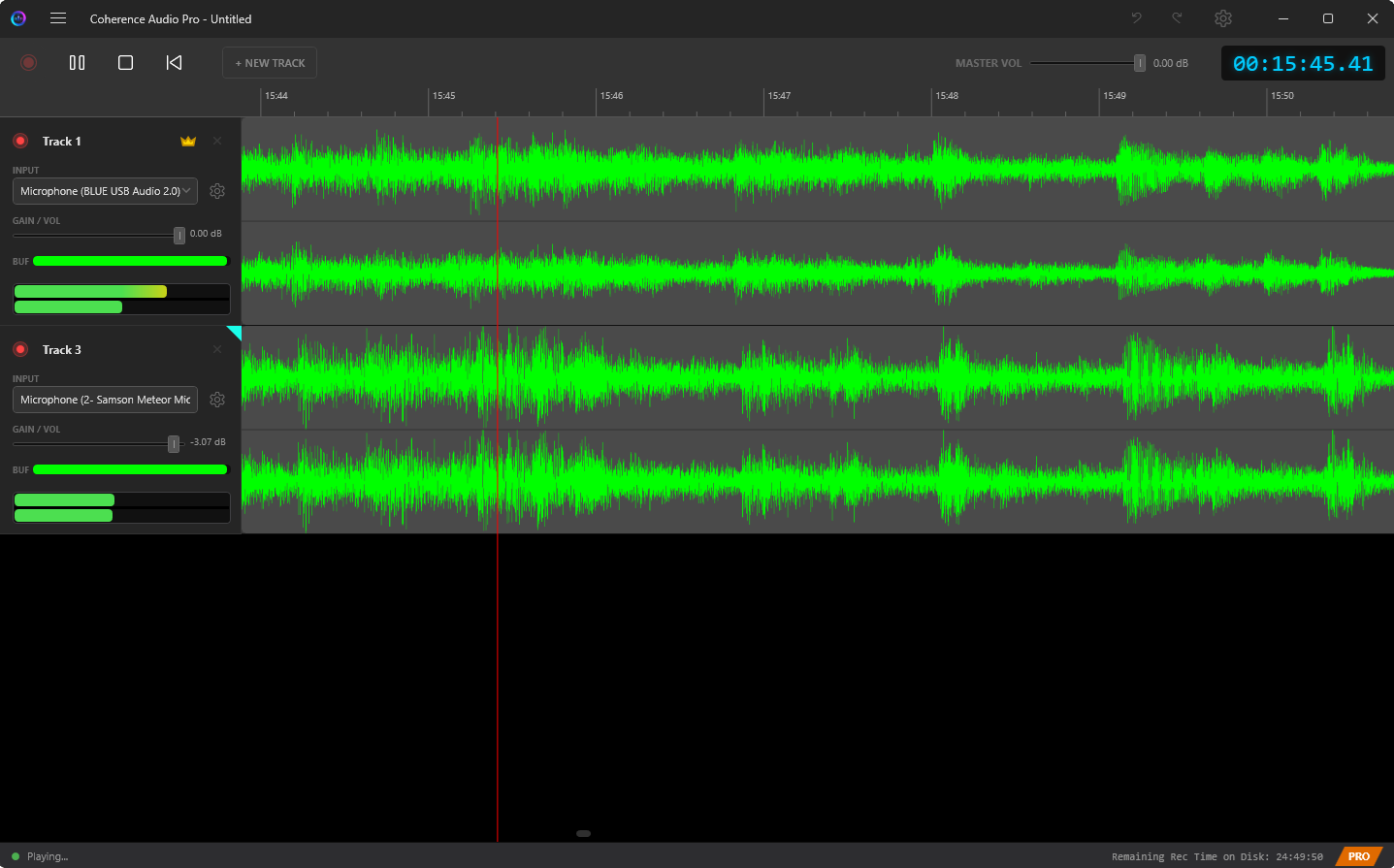
The Ring Buffer and the Overflow Warning
Internally, Coherence Audio maintains a memory ring buffer for each recording track. Audio from the device flows into the ring buffer continuously; a background writer thread drains the buffer to disk.
The ring buffer serves as a cushion: if the disk is momentarily busy, the buffer absorbs the gap and the write catches up. This means brief, transient disk slowdowns do not immediately cause audio drop-outs.
The ring buffer has a fixed size of 3 seconds of audio. If disk writes consistently fall far behind — for example because the storage is too slow or the system is overloaded — the buffer will eventually overflow and samples will be lost.
When this happens, Coherence Audio shows a system overload warning button in the toolbar. Click it to dismiss the warning after investigating the cause.
Common causes of buffer overflow:
- Recording to slow storage (spinning HDD, heavily loaded drive)
- Windows background activity generating excessive disk I/O
Mitigation: Record to a fast SSD. Close unnecessary background applications.
Discontinuity Detection and Gap Filling
Windows WASAPI signals the application when it detects a break in the audio data stream — for example, due to a USB bus spike, a driver glitch, power-saving interruptions, or a very brief device issue. Coherence Audio monitors for these signals on every active recording track.
When a discontinuity is detected:
- Short gaps (a few milliseconds): Coherence Audio fills the gap with smoothly interpolated audio, blending the sample values across the break. The result is a continuous waveform with no audible click at the discontinuity point.
- Longer gaps: Coherence Audio applies a brief fade-out before the gap, fills with silence, and applies a brief fade-in when audio resumes. This avoids hard clicks while making the gap audible.
A discontinuity warning is shown on the affected track’s row so you can see where problems occurred.
Frequent discontinuities are a sign of a problem. Common causes: cheap USB microphones with unreliable USB implementations, Windows USB power saving features, CPU throttling under load, or driver-level buffering issues on low-cost audio chips.
USB Hot-Plug Recovery
If a USB microphone disconnects during a recording session, Coherence Audio:
- Stops capturing audio for that track and marks the disconnection point.
- Continues recording all other tracks normally.
- When you use Device → Rescan Input Devices after reconnecting the device, it re-links the device to the track.
Audio captured before the disconnect is preserved. The gap during the disconnection period cannot be recovered.
After Recording: Latency Compensation and Drift Correction
When you click Stop, Coherence Audio automatically performs two post-processing steps (in order):
-
Apply Latency Compensation — Shifts each clip earlier on the timeline by the configured latency offset for that track. If you set a 15 ms compensation on a particular mic, the clip moves 15 ms earlier.
-
Apply Drift Correction (Pro only) — Resamples each non-master track to align it with the master clock’s timeline. See Clock Sync & Drift Correction for details.
Both steps are pushed onto the undo stack as distinct operations. To undo drift correction, press Ctrl+Z once. To also undo latency compensation, press Ctrl+Z again.
Practical Recording Checklist
Before every session, run through this checklist:
- The workspace root is on a fast SSD with sufficient free space (see Settings → Workspace Path).
- All microphones are connected and visible in the device list.
- Sample rate and bit depth are set correctly for each device.
- Input gain is set so the VU meter shows healthy peaks and the clip indicator does not light during normal levels.
- All intended tracks are armed.
- Latency compensation values are set (or confirmed at 0 ms if not needed).
- If using Pro drift correction, the clock master is designated (see Clock Sync & Drift Correction).
- A short test recording has been made and played back to confirm all tracks are capturing correctly.